An Introductory Tutorial For Encoding QR Codes
QR codes are a type of barcode that can be used to store information such as a number or a URL. They can encode much more information than simple barcodes and enjoy widespread adoption. Just recently, Google Chrome and Microsoft Edge added the ability to easily share images and pages as QR codes. Even some TV commercials now have QR codes embedded within them.
QR codes consist of units called modules. Modules do not have a specific size, but the size of a module should be consistent throughout the QR code. They also come in two varieties: light and dark. Usually, light modules are white and dark modules are black, but this does not have to be the case. In fact, there are sites that allow someone to make a QR code that is a gradient of colors. QR codes also come in various sizes called versions. The larger the QR code version, the more data that can be contained inside of it.
This tutorial explains the coding process of a QR code with a reference example.
Naturally, the first step in encoding data in a QR code is to pick the data to encode. For this tutorial, we will use the phrase HELLO WORLD (Note that this phrase is in all uppercase letters).
We also need to choose an encoding mode for our phrase. Each encoding mode has a different set of allowable characters. While there are some more advanced encoding modes, this tutorial will focus on the four most basic ones and their character sets: numeric, alphanumeric, byte, and kanji. It is also possible to mix encoding modes in a QR code. This is beyond the scope of this tutorial, and our example QR code does not mix encoding modes.
Numeric mode: As the name suggests, this mode only contains the digits 0–9.
Alphanumeric mode: This mode consists of the digits 0–9, the capital letters A-Z, and 9 symbols: $, %, *, +, -, ., /, :, and the space character.
Byte mode: This mode consists of the characters in the ISO-8859–1 character set. It is possible for some QR code scanners to detect UTF-8 in byte mode, but this is not a part of this tutorial.
Kanji mode: This mode uses the characters in the Shift JIS encoding of the JIS X 0208 character set. Shift JIS uses two bytes to encode kanji characters.
In our example, we will use the alphanumeric encoding mode. Incidentally, alphanumeric mode does not allow for lowercase letters, which is why the example phrase is “HELLO WORLD” instead of “Hello World”.
Finally, we need to choose an error correction level. This level determines the maximum percentage of data that is able to be recovered in the event that there is an error reading the QR code. There are four error correction levels: L, M, Q, and H. Error correction level L can recover up to 7 percent of data, while correction levels M, Q, and H can recover up to 15, 25, and 30 percent of data, respectively. For our HELLO WORLD example, we will use error correction level H.
Now we need to determine the minimum acceptable QR code version. A QR code has 40 possible versions which are numbered 1–40. The version determines the size of a QR code, with each version resulting in a QR code that is 4 modules wider and taller than the previous version. The sizes range from 21 modules by 21 modules (Version 1) to 177 modules by 177 modules (Version 40). One can calculate the size of a QR code using the following formula:
QR code size in modules = 4 * (version — 1) + 21
The minimum version of a QR code is dependent on the length of the data being encoded, the encoding mode, and the error correction level. Finding the version can be done by searching the capabilities table for the smallest version that has the same encoding mode and error correction level with a higher maximum character count than the number of characters in the data.
For our example, HELLO WORLD is 11 characters long and we are using alphanumeric encoding mode with error correction level H. This corresponds with a minimum version number of 2. This also means that the size of the QR code is:
4 * (2-1) + 21 = 25 modules
Encoding the Phrase
Next is to encode our phrase into 8-bit groups called codewords. There are four parts to the encoded data: the mode indicator, the character count indicator, the encoded payload, and extra padding. Each part will be explained in detail below.
Mode Indicator
The encoded data starts with a four bit indicator that identifies the mode that the QR code is using, also called the mode indicator. The indicator for each basic mode is listed below:
- Numeric: 0001
- Alphanumeric: 0010
- Byte: 0100
- Kanji: 1000
Since we are using alphanumeric encoding for our HELLO WORLD example, the mode indicator is 0010.
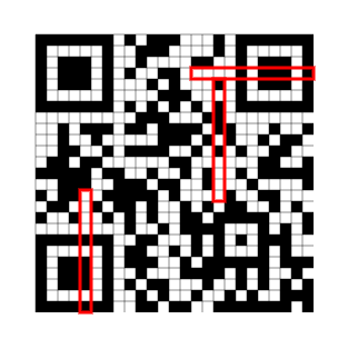
Character Count Indicator
The character count indicator represents the number of characters in the data to be encoded. Additionally, the number of bits used for the character count indicator is dependent on the QR code version and encoding mode. The different indicator sizes can be found in the table below. In our example, HELLO WORLD is 11 characters long, the QR code is Version 2, and we are using alphanumeric encoding mode. Therefore, the character count indicator is the value 11 encoded using 9 bits, or 000001011.
Encoded Payload
Next is encoding our payload data. Each encoding mode has a different method for encoding data. The steps for encoding data in each of our four different encoding modes are described in detail below:
Numeric Mode Encoding
First, the number is broken up into groups of 3 digits. The last group may have less than 3 digits if the length of the number is not divisible by 3. Then for each group, treat the digits as a single number. If the number is greater than 99, convert it to a 10 bit string. If the number is between 10 and 99, convert it to a 7 bit string. Otherwise, convert it to a 4 bit string. For example:
- 291 → 0100100011
- 76 → 1001100
- 4 → 0100
Alphanumeric Mode Encoding
First, the phrase is split into pairs of characters. If there are an odd number of characters, the last pair will only contain the final character. Then for each pair, get the number representation for each character. This can be found in the table of alphanumeric values, shown below:

Afterwards, if there are two characters in the pair, multiply the first value by 45 and add the second character. Then, convert the result into an 11-bit binary string, padding the left with zeros as necessary. For example, if we were to convert the first pair of characters in HELLO WORLD:
H → 17, E → 14
(45 * 17) + 14 = 779
779 → 01100001011
If there is only one character in the pair, convert the single value to a 6-bit binary string. For example, in HELLO WORLD, the number of characters is odd. Therefore, the last character is:
D → 13 → 001101
Byte Mode Encoding
First, the phrase is split into bytes. Then, each byte is converted into an 8 bit binary string. For example, suppose the data was “Hello”. Following the conversion process, we get:
- H → 0x48 → 01001000
- e → 0x65 → 01100101
- l → 0x6c → 01101100
- l → 0x6c → 01101100
- o → 0x6f → 01101111
Kanji Mode Encoding
First, convert the characters to bytes. The byte value of Kanji characters can be found here. Recall that Shift JIS characters are represented using two bytes. For example:
覚 → 0x8A6F
裄 → 0xE5E0
For each character, we subtract by either 0x8140 or 0xC140, depending on the character. Specifically, if the character is between 0x8140 and 0x9FFC, subtract 0x8140; otherwise, subtract 0xC140.
Then, we split the result into the most and least significant byte. For example, the most significant byte for 0x8A6F is 0x8A and the least significant byte is 0x6F. Multiply the most significant byte by 0xC0, add the least significant byte to the result, and convert the result into a 13 bit binary string.
For example, let’s look at the character 覚. Following the kanji encoding steps would result in the following:
覚 → 0x8A6F
0x8A6F - 0x8140 = 0x092F
0x09 * 0xC0 + 0x2F= 0x06EF
0x06EF → 0011011101111
As mentioned earlier, our example encodes the data in alphanumeric mode. Following the encoding steps for that mode, the resulting bytes are detailed below:
(H, E)     --> (45 * 17) + 14 --> 779  --> 01100001011
(L, L)     --> (45 * 21) + 21 --> 966  --> 01111000110
(O, Space) --> (45 * 24) + 21 --> 1116 --> 10001011100
(W, O)     --> (45 * 32) + 24 --> 1464 --> 10110111000
(R, L)     --> (45 * 27) + 21 --> 1236 --> 10011010100
(D)        -->                    13   --> 001101Final Encoding:
01100001011 01111000110 10001011100 10110111000 10011010100 001101
Extra Padding
After encoding the data, we must find the required number of data bits for our QR code. This number is dependent on the version and error correction level of the QR code and can be found in the error corrections table.
Under our current QR code version and error correction level, 16 codewords, or 128 bits, are required. The indicators and encoded data combined is currently 74 bits long; therefore, 54 bits are required as padding.
Terminator of Zeros
First, a terminator of zeros up to 4 bits are required at the end of the encoded data if needed. In other words, if more than 4 bits of padding are required, add 4 zeros; otherwise, add the necessary number of zeros. As mentioned earlier, our example is 54 bits short of the required length. Therefore, we put 4 zeros at the end of the encoded data.
If the encoded data is still not long enough, pad bytes are added until it is. However, before that, the length of our current encoded data must be a multiple of 8. This is done by adding more zeros to the end of the data. For our example, the length of the encoding so far is 78 bits; so, we add 2 zeros.
Pad Bytes
Once again, check to see if the encoded data has reached the required length. If not, pad bytes need to be added until it is. Alternate between adding 0xEC (11101100) and 0x11 (00010001) to the end of the encoded data until it reaches the required length.
In our HELLO WORLD example, we are still 48 bits short of the required length, so we need to add 6 pad bytes.
Afterwards, the bits are split into 8 bit codewords. The final encoded data is shown below:

Error Correction Codewords
Once the data has been encoded, error correction codewords must be generated. These correction codewords are used for detecting and correcting errors in reading the QR code. This tutorial is focused on creating the codewords; the process of detecting and correcting data is beyond this scope.
Before generating the correction codewords, it may be necessary to split the encoded data into groups and blocks. This is needed if the version of the QR code is greater than 1. The number of groups and blocks to split the data into can be found in the error corrections table. For our example, there is one group that has one block with 16 codewords in it.
To generate error correction codes, a method is used known as Reed-Solomon error correction. In order to use this method, we need to understand two concepts: Galois fields and polynomial long division.
Galois Fields
As mentioned in the previous selection, generating error codewords require a basic understanding of Galois fields. Galois fields, also known as finite fields, are essential in areas such as number theory and cryptography. A Galois field consists of a finite set of numbers and mathematical operators that produce numbers that are in the same set.
The QR code specification uses bitwise modulo 2 arithmetic and byte-wise modulo 285 arithmetic. The modulo operator a modulo n is the remainder after a is divided by n. This corresponds to Galois Field 2⁸, also known as GF(256) or Galois Field 256. For the rest of this tutorial, this field will be referred to as GF(256). GF(256) consists of the integers 0–255.
Addition and Subtraction in GF(256)
For every number n in GF(256), n = -n. This not only means that positive and negative numbers are the same, but also that addition and subtraction are equivalent operations. To add or subtract in GF(256), use regular addition and subtraction, then use the modulo operator. As mentioned earlier, GF(256) uses bitwise modulo 2 arithmetic. This is equivalent to using the XOR (exclusive or) operator.
XOR (^ or ⊕) is an operation such that a ^ b = 1 if either a = 1 or b = 1 but not if both do. In other words, it follows these rules:
0 ^ 0 = 00 ^ 1 = 11 ^ 0 = 01 ^ 1 = 0
All addition and subtraction in GF(256) is done using XOR.
Representing Numbers in GF(256) As a Power of 2
Every number in GF(256) can be represented as a power of 2, such as 2³. For every number 2ⁿ in GF(256), n is a number between 0–255. However, every number in GF(256) is itself between 0–255. This presents a problem for numbers such as 2⁸ and 2⁹, both of which are greater than 255. For 2⁸, this is resolved by XORing the number with 285, per QR code specification. Therefore:
2⁸ = 256 ^ 285 = 29
However, this calculation is different for 2⁹. Instead of XORing 512 (2⁹) with 285, multiply 2⁸ by 2. Therefore:
2⁹ = 2 * 2⁸ = 2 * 29 = 58
Generally, calculating 2ⁿ should follow these steps:
- If n = 0, return 1
- Otherwise, calculate 2 * 2ⁿ⁻¹
- If the result from the previous step is greater than 255, XOR with 285
All of the powers of 2 in GF(256) can be found in this table.
Multiplication in GF(256)
In general, two numbers p and q that can be expressed as a power with the same base b can be multiplied by adding their exponents. For example, 3⁴ * 3⁷ = 3⁴⁺⁷ = 3¹¹. This creates a shortcut in multiplying numbers in GF(256). Because any number in the field can be expressed as a power of 2, all multiplication can be expressed as an addition of exponents of base 2.
For example, suppose we were trying to multiply 76 and 43. To do that, we would perform the following steps:
- Convert 76 and 43 to base 2 forms. Here, 76 = 2¹⁶ and 43 = 2²¹⁸
- Add the exponents together. Here, 16 + 218 = 234
- If the result from the previous step, x, is greater than 255, apply x modulo 255.
- Convert the exponent back for the final value. Here, 2²³⁴ = 251.
So, 76 * 43 = 251 in GF(256).
Polynomial Long Division
Polynomial long division is the process by which to divide two polynomials. For QR codes, it is necessary to use the remainder after dividing two polynomials p and q. The process to get that remainder is described below:
- Multiply q by a term such that it has the same first term as p
- Subtract the result from the previous step from p. Set p to this result.
- Repeat Steps 1–2 until q can no longer be multiplied by an integer term to have the same first term as p.
For example, suppose we were to divide (x - 2) into (4x³ + 3x² - 5x + 8). To find the remainder, we would perform the following steps:
- Multiply (x-2) by 4x² and subtract from (4x³ + 3x² - 5x + 8). This results in (11x² - 5x+8).
- Multiply (x-2) by 11x and subtract from (11x² - 5x+8). This results in (17x + 8).
- Multiply (x-2) by 17 and subtract from (17x + 8). This results in 42.
- Since (x-2) can no longer be multiplied by an integer term, the remainder is 42.
Now that the base concepts have been explained, we can move on to the generating the error codewords. To do this, we must get the remainder after dividing a message polynomial by a generator polynomial. This is explained in further detail below.
Message Polynomial
The message polynomial is created by converting a block’s data codewords to integers and using them as coefficients. For example, suppose the data codewords for a message was 01000101, 11110010, 00010001, and 10101011. Converting the data codewords to integers would get us 69, 242, 17, and 171 and the message polynomial would be 69x³ + 242x² + 17x + 171.
Generator Polynomial
The message polynomial is divided by a generator polynomial. A generator polynomial is created by multiplying together (α⁰x -α⁰) through (α⁰x -αⁿ⁻¹) where n is the number of error codewords to be generated and α = 2. To multiply two polynomials in GF(256), do the following steps
- Multiply each term of the first polynomial with each term of the second polynomial as described in the Galois Fields section on multiplication.
- Convert exponents to integers if necessary.
- Add like terms as described in the Galois Fields section on addition.
For example, suppose we were to multiply (x² + 3x + 2) and (x - 4). These would be the steps to do so:
(x² + 3x + 2) → (α⁰x² + α²⁵x + α¹)
(x - 4) → (α⁰x - α²) (Recall that positive and negative numbers are the same in GF(256) so the final term can be positive)
α⁰⁺⁰x²⁺¹ + α²⁵⁺⁰x¹⁺¹ + α¹⁺⁰x⁰⁺¹ + α⁰⁺²x²⁺⁰ + α²⁵⁺²x¹⁺⁰ + α¹⁺²x⁰⁺⁰
α⁰x³ + α²⁵x² + α¹x¹ + α²x² + α²⁷x¹ + α³x⁰
1x³ + 3x² + 2x¹ + 4x² + 12x¹ + 8
1x³ + (3 ⊕ 4)x² + (2 ⊕ 12)x¹ + 8
x³ + 7x² + 14x + 8
For our HELLO WORLD example, 28 error correction codewords must be generated per block. Therefore, we follow the steps to create a generator polynomial where n = 28. The resulting generator polynomial in alpha notation is this:
α⁰x²⁸ + α¹⁶⁸x²⁷ + α²²³x²⁶ + α²⁰⁰x²⁵ + α¹⁰⁴x²⁴ + α²²⁴x²³ + α²³⁴x²² + α¹⁰⁸x²¹ + α¹⁸⁰x²⁰ + α¹¹⁰x¹⁹ + α¹⁹⁰x¹⁸ + α¹⁹⁵x¹⁷ + α¹⁴⁷x¹⁶ + α²⁰⁵x¹⁵ + α²⁷x¹⁴ + α²³²x¹³ + α²⁰¹x¹² + α²¹x¹¹ + α⁴³x¹⁰ + α²⁴⁵x⁹ + α⁸⁷x⁸ + α⁴²x⁷ + α¹⁹⁵x⁶ + α²¹²x⁵ + α¹¹⁹x⁴ + α²⁴²x³ + α³⁷x² + α⁹x + α¹²³
Division Steps
Now that the message and generator polynomials have been created, divide them to get the error codewords. To do so, perform the following steps, which are the steps for polynomial long division, modified to take into account GF(256) operations.
- Multiply the message polynomial by xⁿ where n is the number of error correction codewords to be generated and multiply the generator polynomial by
- Multiply the generator polynomial by the lead term of the message polynomial. The process of multiplying two polynomials is explained in the Generator Polynomial section.
- XOR the result of the previous step with the message polynomial and discard the lead 0 term. This is the new message polynomial.
- Repeat the two previous steps n-1 times where n is the number of data codewords. The coefficients of message polynomial at the end are the error codewords.
In our example, there is only one block so there is only one set of error codewords. However, if there is more than one block, then error codewords need to be generated for every block of data.
Now that we have created error codewords, we can place them into the QR code. However, we may need to interleave the data and error codewords. This is explained in the next section.
Interleaving Data Blocks and Error Codewords
If there is more than one total block of data, the data and error codewords have to be interleaved together. To interleave the data, start with the first data codeword of the first block. Then, add the first data codeword of the second block, the third block, and so on until all of the first data codewords have been added. Add the second data codeword from all of the blocks in the same order, and continue until all of the data codewords have been added. Then do the same for the error correction codewords until all of them have been added.
After the messages have been interleaved, there may still be a number of zeros to add to the end of the data, known as remainder bits. The number of remainder bits to add is dependent on the QR code version and can be found in the remainder bits table. Since our example uses Version 2, 7 remainder bits need to be added to the end of the data.
Now we can move on to filling in the QR code itself. For our reference example, light modules are white and dark modules are black. There will also be gray modules in some images that represent unfilled modules. Along with data modules there are different patterns that are to be included. These patterns will be described below:
Finder Patterns
Every QR code has three finder patterns, which consist of an outer dark square, a middle white square, and an inner dark square. The outer square is 7 modules wide by 7 modules tall, while the middle and inner squares are 5 by 5 and 3 by 3, respectively.

The finder patterns are always placed on the top left, bottom left, and top right corners of the QR code. Given our HELLO WORLD example, this is how the finder patterns would be placed:

Separator Patterns
On the outside of the finder patterns are lines of light modules called separator patterns. The purpose of this pattern is to separate the finder patterns from the rest of the QR code, hence the name. The separator pattern are 1 module wide and are placed on the sides of the finder patterns that are facing towards the inside of the QR code.

Alignment Patterns
QR code versions larger than 1 are required to have alignment patterns. An alignment pattern is similar to a finder pattern. It has a 5 module by 5 module dark square, an inner 3 module by 3 module light square, and a single dark module in the center.

The alignment pattern location table holds the locations of the alignments, which are dependent on the version of the QR code. The values in the table represent row and column values of the center of each module. Each alignment has a row and column coordinate that is one of the values. For example, the QR code version for our example has the values of 6 and 18. This corresponds to center coordinates of (6, 6), (6, 18), (18, 6) and (18, 18).
However, no alignment pattern is placed in a location that overlaps with the finder and separator patterns. This means that no alignment patterns are placed at (6, 6), (6, 18), or (18, 6).


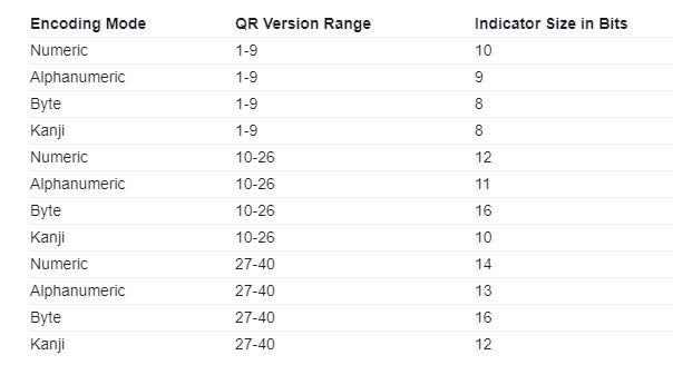
Timing Patterns
Each QR code has one horizontal and one vertical timing pattern. These timing patterns consist of alternating dark and light modules which always start and end with a dark module. They are placed between the separators in the seventh row and the seventh column of the QR code.

Dark Module
Every QR code has a single dark module just to the right of the bottom left separator. Specifically, the module is at column 8 and row 4*(v-1)+13where v is the version of the QR code. For our example, this is row number 17 since we are using QR code version 2.

Version Information
QR codes with a version of 7 and higher contain two areas that store version information. One area is a 6 module by 3 module block above the bottom left separator. The other area is a 3 module by 6 module block to the left of the top right separator. The 18 bit version string consists of 6 bits for the version number and 12 error correction bits.

The layout of the version information string for each area is detailed below.
Top Right Version Block          Bottom Left Version Block  | 17 | 16 | 15 |             | 17 | 16 | 15 | 14 | 13 | 12 |
  | 14 | 13 | 12 |             | 11 | 10 |  9 |  8 |  7 |  6 |
  | 11 | 10 |  9 |             |  5 |  4 |  3 |  2 |  1 |  0 |
  |  8 |  7 |  6 |
  |  5 |  4 |  3 |
  |  2 |  1 |  0 |Index 0 is the left most bit while index 17 is the right most bit.
Generating the error correction bits for the version information string is somewhat different than generating error codewords. The bits are still created by dividing a message polynomial by a generator polynomial, but the details are somewhat different. These differences are discussed below.
Version Message Polynomial
The message polynomial is the 6 bit version number. Instead of treating it as a list of coefficients in alpha notation, we leave it as a binary number.
Version Generator Polynomial
Per the QR code specification, the generator polynomial for creating version error correction bits is x¹² + x¹¹ + x¹⁰ + x⁹ + x⁸ + x⁵ + x² +1. This is represented by the binary string 1111100100101.
Division Steps
Pad zeros to the right of the message bit string until it is n + m bits long, where n is the length of the message bit string and m is the number of desired error correction bits. Remove any leading zeros on the left side of the message bit string. Then, repeat these steps until the length of the message bit string is less than or equal to m.
- Pad zeros to the right of the generator polynomial bit string until it is the same length as the message bit string.
- XOR the result of the previous step with the current bit string.
- Remove leading zeros from the left side of the result from the previous step. This is the new message bit string.
Once this is done, pad the message bit string with zeros on the left until it is exactly m bits long. These are the error correction bits. Put the version bits before these bits to get the whole version information string.
A version area is not included in our example QR code since it is a version less than version 7.
Version Table
Instead of calculating the version string manually, all the possible version information strings can be put into a table. From there, one can choose the version information string that matches the QR code version.
Reserving Format Information
Before placing the encoded into a QR code, space must be reserved for the format information. The space cannot be filled yet because the format information is based on the QR code mask pattern, which will be discussed in a later section. The reserved space is illustrated below, with the separators, timing patterns, and the dark module shaded for reference.
Placing Encoded Data in QR Code
Now the encoded data can be placed in the QR code. Start at the bottom left module and move upward in a 2 module wide column while filling in the modules from right to left. The order in which to fill the data modules is illustrated below.

Once the top of the QR code is reached, another 2 module column is started to the left of the previous one. Move downward instead of upward while continuing to fill in the modules from right to left.

Encountering Function Patterns or Reserved Areas
When a function pattern such as an alignment pattern or a reserved area like the format area is encountered, simply skip the module and proceed in the current direction.
Encountering the Vertical Timing Pattern
The exception to encountering function patterns is the vertical timing pattern. When on the same column as this one, start the new column to the left of the timing pattern. In other words, do not overlap a column with this function pattern.
For our HELLO WORLD example, once placing the data modules is completed, the QR code should look similar to the below illustration.

Mask Patterns
To ease the scanning process for a QR code reader, QR codes have a mask pattern that is applied to the data and error correction modules. In other words, mask patterns do not affect finder patterns, timing patterns, alignment patterns, etc. Masking a module simply means to switch a dark module to a light module and vice versa. For a QR code, there are eight possible mask patterns which are described below as formulas. For any given module, a mask is applied if the formula equals true for a module’s row and column index.
- Pattern 0:
(row + column) % 2 == 0(row and column are both odd or both even) - Pattern 1:
row % 2 == 0(even numbered rows) - Pattern 2:
column % 3 == 0(every third column) - Pattern 3:
(row + column) % 3 == 0(sum of row and column is divisible by 3) - Pattern 4:
(floor(row / 2) + floor(column / 3)) % 2 == 0 - Pattern 5:
((row * column) % 2) + ((row * column) % 3) == 0 - Pattern 6:
(((row * column) % 2) + ((row * column) % 3)) % 2 == 0 - Pattern 7:
(((row + column) % 2) + ((row * column) % 3)) % 2 == 0
Side note: Here are definitions for some of the math operations used in the formulas
a % nrefers to the modulo operation which was explained in the Galois Fields sectionfloor(n)refers to the floor operation, or the greatest integer less than or equal to n
To find the best mask pattern to use, apply one of the mask patterns to a QR code. Then, the QR code is evaluated based on four conditions, and a score is given. This is done for all eight mask patterns; the best mask pattern is the one with the lowest score. Note that the evaluation applies to the whole QR code, not just the masked areas. Because of this, we will need to fill in the format section of the QR code before proceeding to evaluate it.
Filling in the Format Area
The format string is 15 bits long an consists of 2 bits for the error correction level, 3 bits for the mask pattern, and 10 error correction bits. Once those bits are generated, they are XORed with the pattern 101010000010010. This is explained in further detail below.
Error Correction Level Bits
The first two bits of the format string specify the error correction level of the QR code. Since our example has error correction level H, the error correction level bits are 10. Below lists the error correction level bits for the four possible error correction levels.
- L: 01
- M: 00
- Q: 11
- H: 10
Mask Pattern Bits
The next three bits represent the mask pattern number. For example, mask pattern 3 converts to 011 while mask pattern 6 converts to 110.
Format Error Correction Bits
Now 10 error corrections bits are generated using the same process as creating error correction bits for the version string. In this case, the message polynomial is the error correction level bits and the mask pattern bits represented as a 5 bit string. The generator polynomial is x¹⁰ + x⁸ + x⁵ + x⁴ + x² + x + 1, or 10100110111.
Afterwards, XOR the 15 total bits with the pattern 101010000010010 to get the final format information string.
Filling In the Format Space
The below illustration shows how to fill in the format string into the QR code for our QR code example. Index 0 represents the left most bit while index 14 represents the right most bit. The separators and timing patterns are shaded in for reference.

Format Table
Just like the version information string, all of the possible format information strings can be put into a table. Now that we know how to fill in the format areas, we can evaluate a QR code mask pattern.
As mentioned earlier, choosing the best mask pattern is dependent on four evaluation conditions. Each condition — detailed below — has a different score which is then added together to create a final penalty score for that mask pattern. To illustrate each evaluation condition, we will use our HELLO WORLD QR code with mask pattern 0.
Evaluation Condition #1
This condition checks for five or more consecutive modules of the same color in every row and column. Each such time the pattern occurs, 3 is added to the score. For every module afterwards that is still the same color, add 1. In our example, the total score for all of the rows is 102, and the total score for all of the columns is 108. Therefore, the final score for evaluation condition 1 is 102 + 108 = 210. Below highlights the locations of the row and column condition patterns. The initial five modules of the same color are highlighted in red and the additional same color modules are highlighted in teal.


Evaluation Condition #2
This condition checks for every 2 module by 2 module square of the same color. For every one, 3 is added to the score. In our reference QR code, there are 56 such squares, highlighted below. Therefore, the final score for this evaluation condition is 56 * 3 = 168.

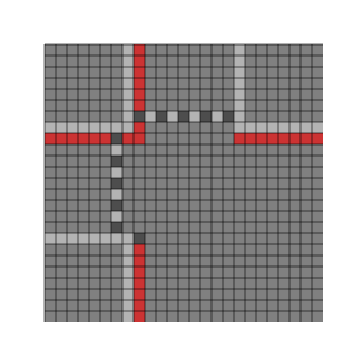
Evaluation Condition #3
This condition checks for patterns that are similar to the finder patterns. Specifically it looks for the two patterns that are shown below. For every pattern that is found, add 40 to the score.


In our example, this pattern appears 3 times. Therefore, the final score for this evaluation condition is 40 * 3 = 120.
Evaluation Condition #4
This condition evaluates the ratio of light and dark modules. To get the score for this condition, do the following steps:
- Calculate the percentage of dark modules in the QR code.
- Determine the previous and next multiple of five of the percentage in step 1. For example, if a QR Code has 38% dark modules, the previous multiple is 35 and the next multiple is 40.
- Subtract 50 from the numbers in step 2. Then, take their absolute values.
- Divide the numbers from Step 3 by 5
- Take the smaller of the two numbers and multiply it by 10. This is the final score for this evaluation condition.
Now given our QR code example, let us calculate the evaluation score.
- There are 312 dark modules and 625 total modules in the QR code, meaning that the percentage of dark modules is
(312 / 625) * 100 ≈ 49.92 - Based on the previous step, the previous multiple of five is 45 and the next multiple of five is 50.
- Based on the previous step, the values for this step are
|45-50| = 5and|50-50| = 0 - Based on the previous step, the values for this step are
5 / 5 = 1and0 / 5 = 0 - 0 is the smaller of the two values. Therefore, the final score for this evaluation condition is
0 * 10 = 0
Adding all of the score for each evaluation condition, we get the final score of 498 for mask pattern 0. Then, apply all the evaluation condition for the seven other mask patterns and choose the mask with the lowest score. In the case of our HELLO WORLD example, this would be mask pattern 5.
Finally, there is a quiet zone placed on the outside of the QR code, and we have our final QR code, shown below.

An acknowledgement to the Thonky QR Code Tutorial, a great tutorial resource that helped me to conceptualize the steps in creating this tutorial: https://www.thonky.com/qr-code-tutorial/data-encoding
If you want an interactive tutorial to play with example QR code settings, check out my Observable notebook on encoding QR codes: https://observablehq.com/@zavierhenry/encoding-qr-codes
